I have never had a “base” station for 2 meter... not technically speaking. The only thing I have ever had is a “go” box that I moved from the car to the shack. However, I probably need to explain what I mean by “shack.”
I have seen pictures of other’s “shacks”… just let me say, my ham “shack” is NOTHING like what I have seen. In the beginning... when I first started, my mobile 2 meter rig was setting on top of the clothes dryer with a coax running out the door to a copper j-pole mounted on a tripod. I couldn't afford a "real" antenna, so I went online and found plans for making a 1/2 inch copper j-pole. For a few bucks, a little effort, and some horrible soldering, I was on the air. It was powered by a 12v battery that I stole out of my boat.
My next big step was to get a “box”. I got one of those aluminum cases that you can purchase at Home Depot. I was moving up… With a smaller 12v battery, and a 15 amp power supply (Christmas gifts) I could move wherever I wanted. I finally purchased a mobile whip antenna and my shack became my car. Most of the time I was mobile / stationary. Using Anderson Powerpole connectors (again, a Christmas gift - who would have thought that Santa made big boy toys too??) I was able to easily get power from the car or from the power supply or virtually any 12v source.


During the fall of ’09 and the spring of ’10 I began to make some major "elbow grease" improvements to my man cave / garage. My 2 meter box would find a new home. However, I came to a point where I wanted to make changes to the “box”. What I was using was working, but it had a lot of drawbacks. The main problem was a lack of storage. Assorted wires, tools and such could not travel in the box. What follows is an account of that change.
The box I chose to use was a 10 x 12 x 18 inch Dry Box that I purchased from Gander Mountain. Its side walls were not quite as thick as I would have liked, but I knew that a partition wall that I was planning for the interior would provide considerable strength and stability.
After placing the box in several different locations (car / man cave) to determine what area inside the box would be occupied by the 2m Yaesu FT2800, I decided an end rather than side location would work best. This was not the most efficient use of interior space, but it was the most appropriate for how I would be placing the box. The new Go-Box has a lot of capacity, so I knew I could afford this "less-than-perfect-usage-of-space" location for the radio.
I also had to think about the best location for my cooling fan (which I stole from an old non-working computer CPU. The mounting bracket that I had made previously was slightly modified so that it now mounted to the original radio mounting bracket. I wanted to make sure that I didn't stifle air circulation around the massive heat sink that is so prominent on the FT2800.

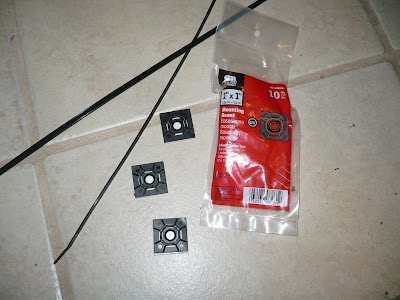
Next was to figure out where to mount the 7.5 amp/hr battery and the 15 amp MFJ power supply. While picking up some cable ties at the Depot I spotted some “mounting bases”. I determined that these would work well to secure the battery to the base of the box. I wanted to use epoxy instead of the sticky tabs on the bottom of the bases. I drilled 3/32 holes in the corner of each base so that the epoxy would ooze up through the holes and provide a better attachment.


The divider wall was made from a small plastic “serving tray” that I found at GFS. My first attempt was to use a thin sheet of plexi glass. That ended badly, but the brown serving tray worked perfectly as my raw material for what would become my wiring/switch panel/box support bulkhead... you get the idea.

My power distribution box was a plastic electric utility box cut to accommodate a small Anderson Powerpole chassis mount fixture. This became basically a poor-man's RigRunner.

The antenna connection was made by using a “thru-the-box” mounting. Because of the wall thickness of the box, all through the wall holes were “washered” appropriately to give the necessary support.

Two switches were needed. The one on left is for power distribution. Center position is “off”. Left provides power from the 15 amp power supply. Right position provides power from the 12v battery. The switch on the right controls the cooling fan. The FT2800 has a tendency to get hot when TXing for long periods at 65 max watts. When it gets hot, signal quality has a tendency to deteriorate. I don’t use the fan when just listening, but when I start moving a lot of traffic, it is always on. Because the fan was designed to be used in conjuction with computer electronics, it is very clean electronically. I have never heard any complaints about my signal with regards to fan related noise.

The final assembly is done and is working as expected. As with anything connected to Amateur Radio, I am already thinking of improvements. But, I am satisfied with the project as it is now. It suits my needs better than my previous box, and I now have the additional storage room that was needed.

No comments:
Post a Comment